Articles By Our Members
Radio Frequency Interference (RFI) Suppression in Model Boats
by David Harrison, September 2005
Introduction
This article discusses the sources of Radio Frequency Interference (RFI)
in model boats, how this is propagated to sensitive electronics and suggests
several techniques for minimizing its effects. The information here comes
from common sense, sound electrical/electronic engineering practices, model
boat books and the practical experience of fellow model makers. I have just
gathered it all together in one place. Particular thanks is given to Ken
Huntington of our club for good information on this topic.
In model boats, there are several sources of radio frequency
interference. The most important one is the RFI generated by the main
electric propulsion motor(s). A secondary, less important, source is the
movement of metal surfaces (especially dissimilar metals) across each other.
A minor one, usually of no significance, is the ESC microcontroller (a small
microprocessor) and its surrounding circuitry (any digital circuitry has the
potential to generate RFI due to the switching current of the digital
signals).
Electric Motor Generated RFI
The information in this article relates to the usual brushed electric
motors used for model boat and submarine propulsion. This does NOT apply to
brushless motors.
Brushed motors generate RFI by two mechanisms:
- The commutator switching current to the armature windings causing sharp
current spikes in the supply leads.
- The commutator arcing (sparks) causing radiated RFI through the air.
Sharp current spikes are generated every time the commutator gaps pass
under the brushes due to the sudden inrush of current into its corresponding
armature winding. The current spikes, being of very short duration, contain
many high frequency energy components that can extend well into the hundreds
of MHz, depending on the speed of the motor, number of motor poles etc.
These current spikes can be propagated back into the R/C equipment by two
mechanisms.
- The current spikes will manifest themselves as voltage spikes at the
battery, and at any point along the length of the wire due to the non-zero
resistance and inductance of the wire. These voltages can find their way
directly back into the R/C receiver and servos by the receiver supply wires.
- The supply wires themselves will act as antennas radiating RF EMI
(ElectroMagnetic Interference) back to the receiver through the air.
Similarly, the arcing at the commutator can propagate directly through
the air to the R/C equipment. Arcing is caused by the abrupt switching of
current at the brush/commutator gaps and also by the generator effect of the
fast turning windings generating "back EMF" (Electro Motive Force - i.e.
voltage). Do you remember that the very first wireless transmitters had a
very large spark gap to generate the RF signal?!
As well as the receiver and servos containing sensitive electronics, the
speed controllers (ESCs) do as well, containing a microcontroller
Suppression Techniques
RFI suppression techniques target the two propagation mechanisms i.e.
conducted interference through the supply wires and direct radiation through
the air.
Reducing Conducted RFI through the Supply Leads
Suppression Capacitors
Solder a 0.1μF capacitor across the motor terminals and a 0.1μF
capacitor from each motor terminal to the motor can. The motor can will
likely not heat up well enough with a regular soldering iron to take the
solder well, so often some mechanical means of attaching the capacitor wires
must be found. The capacitors create a low impedance (i.e. AC "resistance")
to the high frequency RF signals, but no DC resistance. Do not use
capacitors much larger than 0.1μF since their charging and discharging
currents put an extra load on the ESC output transistors. Be sure to use
good high frequency capacitors such as ceramic. Never use electrolytic or
tantalum capacitors as these do not have good high frequency characteristics
and they are polarised (they have + and - leads and can only be connected
one way round). The voltage rating of the capacitors is usually not an
issue since commonly available ceramic capacitors are rated at about 50V.
Quite often the above capacitors are installed by modelers, but the
following tips will make them much more effective.
- Keep the capacitor leads as short as possible. If you have to compromise
between short motor can side versus brush connector side, always keep the
brush connector side as short as possible.
- Always connect the motor can(s) to the negative battery supply lead. If
you do not connect your motor can to anything other than the suppression
capacitors, then it will act as a big fat antenna radiating the RF
interference coupled into it by the capacitors! Exactly the opposite of
what you want!
- "Ground" the motor can(s) by connecting them to your propeller shaft
stuffing box (prop. shaft tube). Make sure the propeller end of the stuffing
box has a small area without paint to make contact with the pond water.
Although the pond is not a great electrical conductor, it does act as a weak
"ground plane," thus dissipating the can motor RF interference signals to
"ground".
If you make the -ve battery or ground connections suggested, keep
the wires as short as possible otherwise they may act as antennas
themselves.
A note about pond water:
Pure water is a weak conductor. Dissolved solids such as salt and other
acid or alkaline compounds greatly increase its conductivity due to free
ions making it a weak battery electrolyte. Thus sea water is a pretty good
conductor, relatively speaking.
Pond water is somewhere in between, but with all the gunk we find in it,
it is probably a better conductor than your average bathtub full of city
water. We all know that you stand the risk of electrocution if an
electrical appliance falls into the tub and you are in it!
Thus you can see that the pond surface acts somewhat as a ground plane.
If it were a great conductor, then R/C submarines would never work because
the R/F transmitter signal would never penetrate the surface.
Ferrite Beads
A further technique for reducing both conducted and radiated RFI is to
put ferrite beads on the motor supply leads as close to the motors as
possible. Both supply wires should go through one bead. Ferrite is a
non-metallic ferrous (iron) compound that greatly increases the magnetic
flux around and through it. The effect of placing them on the supply leads
is to increase their inductance, which acts as a "choke" to the RFI signals
in the wire. If the beads are large enough, it is even better to wind both
supply leads through and around the bead once to make a kind of elementary
transformer. In this way, the current spikes in one wire will cancel out
the current spikes in the other wire, since the current will be going in the
opposite direction.
Ferrite beads are often hard to find, especially in sizes large enough to
accommodate the heavy wire gauges (e.g. 12AWG) necessary for fast electric
motors.
Electronic surplus store are usually the best source for these. In
Ottawa you can try ADD Electronics, on Armstrong Avenue, near the Parkdale
market. The beads are often shaped like a short thick walled cylinder.
They cost about $1 each. The large bulges in computer monitor cables near
the monitor end also contain ferrite beads so if you have a useless monitor,
cut the cable open and see what you find. Alternatively, they can be
obtained from Digi-Key (ca.digikey.com) - part no.
240-2080-ND
for about a dollar. Shipping and handling charges apply though.
Transient Suppressors
Transient suppressors (also known as transient voltage suppressors or
transorbs) are like two series back to back zener diodes. Thus they are
bi-directional and will clamp voltage transients to their "zener" voltage,
e.g. 15V. They can be very effective in reducing RFI by connecting them
across the motor terminals (again with very short leads) in addition to the
capacitors. They are available in a variety of voltage and power ratings.
The voltage rating should be chosen to be just a little above your maximum
possible battery voltage (taking into account possible overcharging). Thus
for a 12V gel battery which can get up to about 14V when fully charged, a
15V rating is appropriate. If you are running 7.2V batteries, a rating of
9V is OK and for a 6V system use 7.5V. Again, these are somewhat hard to
find - Digi-Key has them e.g. part no.
P6KE15CALFCT-ND
for a 15V 600W device. Ken Huntington in our club sometimes has them on
hand.
Shared Ground and Power Wiring
Shared ground and power wiring is when two or more connections are made
to the -ve and +ve battery terminals at different locations along the supply
wires. Also a conducting loop can easily be formed if there are multiple
return paths in the wiring. If any part of the shared wire or loop carries
high motor currents, the resistance of the wire, although small, can create
small spiky voltage drops along the wire. If that same wire is shared by
electronic modules, then the supply voltage to that module becomes spiky as
well. Ideally, all connections to the battery should be made in a "star"
configuration so that wires are not shared between motors and electronics.
In practice this is difficult to achieve, especially when the typical BEC
(Battery Eliminator Circuit) in the speed controller is used to supply power
to the receiver. We usually use a BEC, if one is available, but that does
mean the receiver shares its ground line with the ESC supplying high
currents to the motors.
Example Photos
Photo 1 - motor connections:
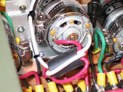
Note the capacitors and ferrite bead. The transient suppressor can be
seen just below the motor end bearing. The hose clamp is used to clamp a
small piece of thin brass bar to the motor can. The capacitor wires are
soldered to the piece of brass, not the actual motor can.
Photo 2 - Ground connections:
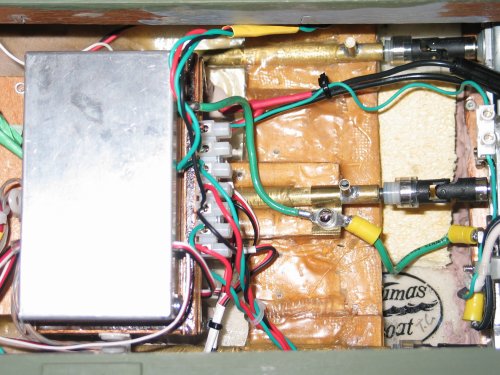
Note the aluminum receiver box and the brass clamp around the centre
propeller stuffing box. Also notice the SHORT thick green grounding wire
between the stuffing box and the receiver box and between the stuffing box
and the aluminum motor mounting plate.
Reducing the Effects of Radiated RFI
Radiated RFI can be reduced by keeping all possible radiating antennas,
i.e. motor supply leads, as short as possible. This also helps to reduce
the voltage loss due to series resistance, although this is usually
negligible if you use 12AWG wire.
The other obvious method of reducing the effects of radiated RFI are to
keep the sensitive electronics (receiver, servos, speed controllers) as far
away from the motors and their supply leads as possible. Obviously, in the
case of the ESCs, these cannot be kept too far away, otherwise the supply
leads will act as longer antennas. Generally keep the ESCs away from the
receiver (in the opposite direction away from the motors).
I choose to mount my receiver in a grounded aluminum box to reduce RFI
radiating directly into the receiver.
Also keep the receiver antenna wire as far away as possible from the
motors, their wires and the ESCs. If your motors are heavy duty, high
current types, then the majority of the antenna wire should be vertical to
get a better signal/noise ratio. This may present a problem in some scale
models, but modelers are usually quite ingenious. Use a mast, a scale
antenna, crane jib etc.
Model Submarines
The above information obviously pertains to model submarines even more
so, since space is usually very limited and the effects of loss of control
due to RFI are much more dramatic than with a surface vessel. Thus pay
particular attention to all the above techniques for RFI reduction.
Mounting Electronics
Although this is not directly related to RFI, all model electronics
should be mounted with a degree of vibration isolation. Model boats,
especially fast ones, have a considerable amount of mechanical vibration
inside the hull. Over a long period of time, this vibration can weaken soft
soldered joints, making them unreliable and even open circuit.
Thus mount your receiver in a bed of rubber or polyurethane foam inside
your receiver box. Always use the rubber grommets supplied with your servos
for their mounting and keep the servo bodies from touching adjacent
surfaces. For receiver box and ESC mounting I use self adhesive Velcro.
This may sound crude, but it provides a bit of vibration isolation and
usually the adhesive on the Velcro strips is quite aggressive, providing a
strong attachment.
David Harrison
|